Interacting Enclosures: A Physical Prototyping Project
Myself and teammate James Gan were tasked with creating interacting PCB enclosures, with a focus on a relationship of how the two parts meet and connect. It was determined early on that I would create the dock portion and James would make the pod. We collaborated on the overall design together and James also created the Space Needle portion. The design constraints for this project were as follows:
Two enclosures must meet and interact for a conditional result ie. blinking led variations
Enclosures must house a pcb (adafruit feather 328P)
Enclosures must snap fit or combine together with a guide
USB port must be exposed
Battery door must be removable
Enclosures should be unique and ideally novel in some way
Priority should be in fit and finish of the physical enclosure interaction and detail. ie. Tolerances must be tight

First draft sketch
A Candle from The Future
The Space Needle night light is a memento in honor of Seattle, designed to light your way from your bedside table in the night, without waking your loved ones. The dock charges the pod, and when the pod undocks, it lights the way to your midnight snack.
Above is a sketch of the original design, including some outlines of resources, challenges, and a rough form the design could take.
Sketch 2
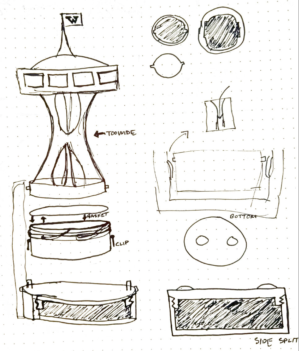
This sketch begins to look at how the dock enclosure may secure the battery and pcb inside. At this stage we began to consider how might we make this dust or even water tight? We really wanted to focus our design energy on the quality of the enclosures themselves. Without further ado, let’s jump into Autodesk’s Fusion360…
Modelling
Creating the enclosures was a top priority and the original focus was on securing the feather in an enclosure with a battery door. A nice YouTube video walked me through creating the threading needed for the lid here: https://youtu.be/uYt9Q5X0t2o
The threading turned out really great on the first try, and I was incredibly surprised by that. I realized my first attempt at a light guide was too small, my prongs for the feather were too flimsy and that my pcb was not close enough to the USB port. I also realized the dock need to be a bit deeper in case of additional leds. The magnet holder design was poor and broke after removing the PVA support materials so I changed the design for that as well. I also moved the charge port to the middle. It was originally offset to assure correct terminal alignment however, the placement of a detent for the fit would resolve this. I also decided that since the connections of the sliding charger contact points will be soldered to wires, these will twist/untwist better if it’s centered.

Dialing in the measurements…
Measurements and Expansion
It was now time to get more serious about the size and placement of things. I took some more notes in my sketch book of for future iterations, and began to conceive a better idea of the fitment for the dock to the pod. Originally it had two inward divets but the design for the pod ended up being a single divet so that it would be directional. It was male by nature and outward by the time it got to Fusion360.
After this iteration, my collaboration James would take the model and create his side, with the Space Needle abstraction.

Lofi Prototypes
At this time we began to scrap together some lofi protoypes of the structure with recycled parts and sculpted foam. The foam sculpting process is a lot of fun and I plan to use it again in the future.

Space Leggies
After creating some rough forms, we began imagining how we might laser cut them. This is a design we didn’t go with, but these are designed to fix together in an X pattern, and function as light guides due to a milky acrylic color.
Fighting Le Resistance … of 3D printers….
Progress
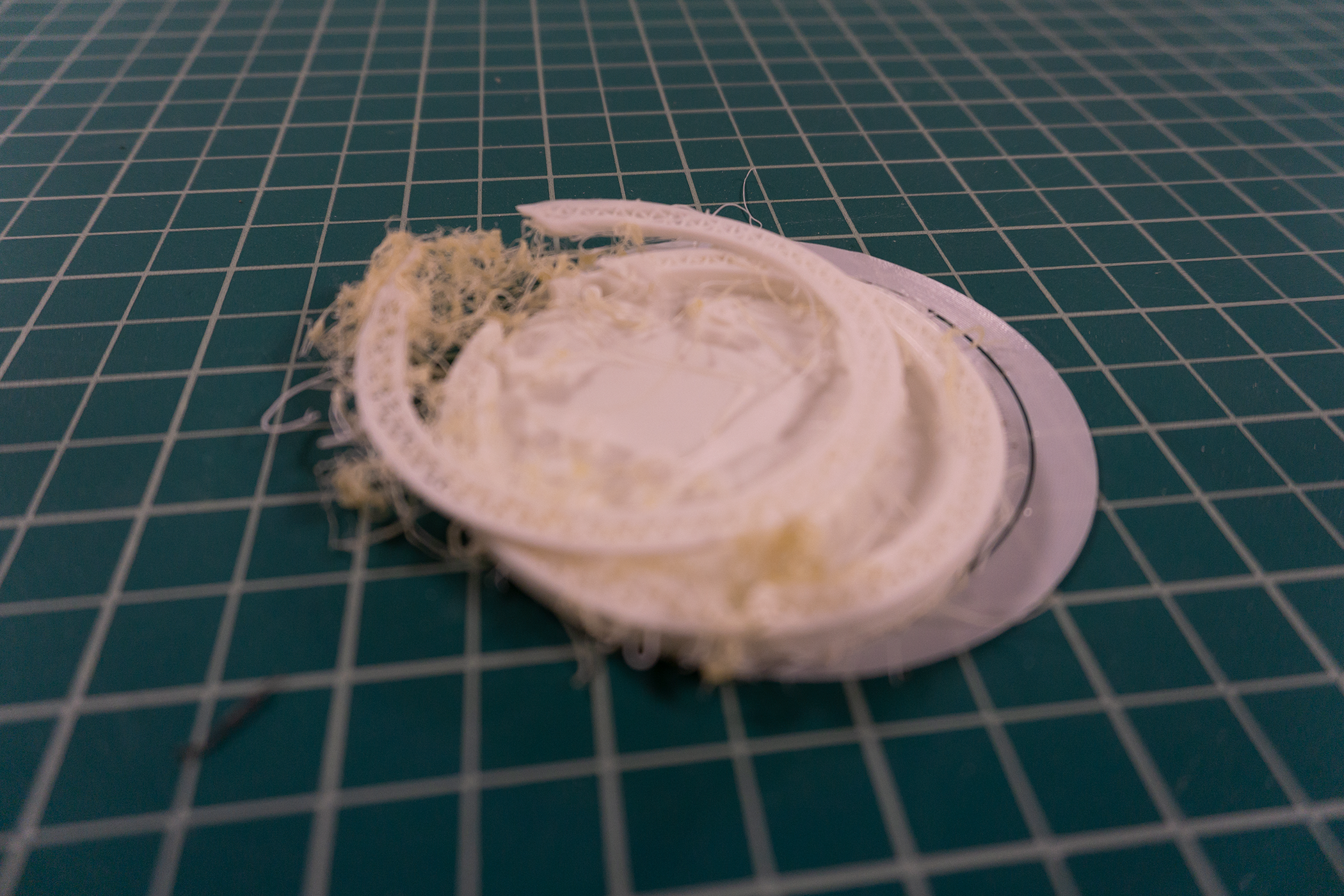
After struggling a bit with the printers, I was able to get a print that was more fully formed…yet deformed. This was a new filament and the temperature of the nozzle might not have been quite right. The light guide was bigger, but still too close to the USB port. The holes for the PCB were still a little big, but we also have now rolled in the battery mounts. These were a bit weak, so I planned for fillet on the next iteration. The proximity of the PCB is good in this iteration.
MORE BETTER
This was one of the better iteration of the light guide, but it was too darn close to the USB port again. This caused another print problem. The prongs for the PCB mount were too close this time as well. I laser cut multiple GIX X’s of various sizes to see if I could squeeze something in. This seemed more efficient than tinkering with the tolerance of a 3D print.

Still moving things around
Lots of Little Changes
At this point, it was mostly moving things around, getting tolerances right. I recessed the PCB more into the floor of the bottom of the enclosure to make room for a bigger USB port. I also began to ponder molding a silicon needle for the top. (as a stretch goal) The light guide was really giving me trouble at this stage, mostly due to an issue I was having in Fusion360 with the plane placement.
Next Please!
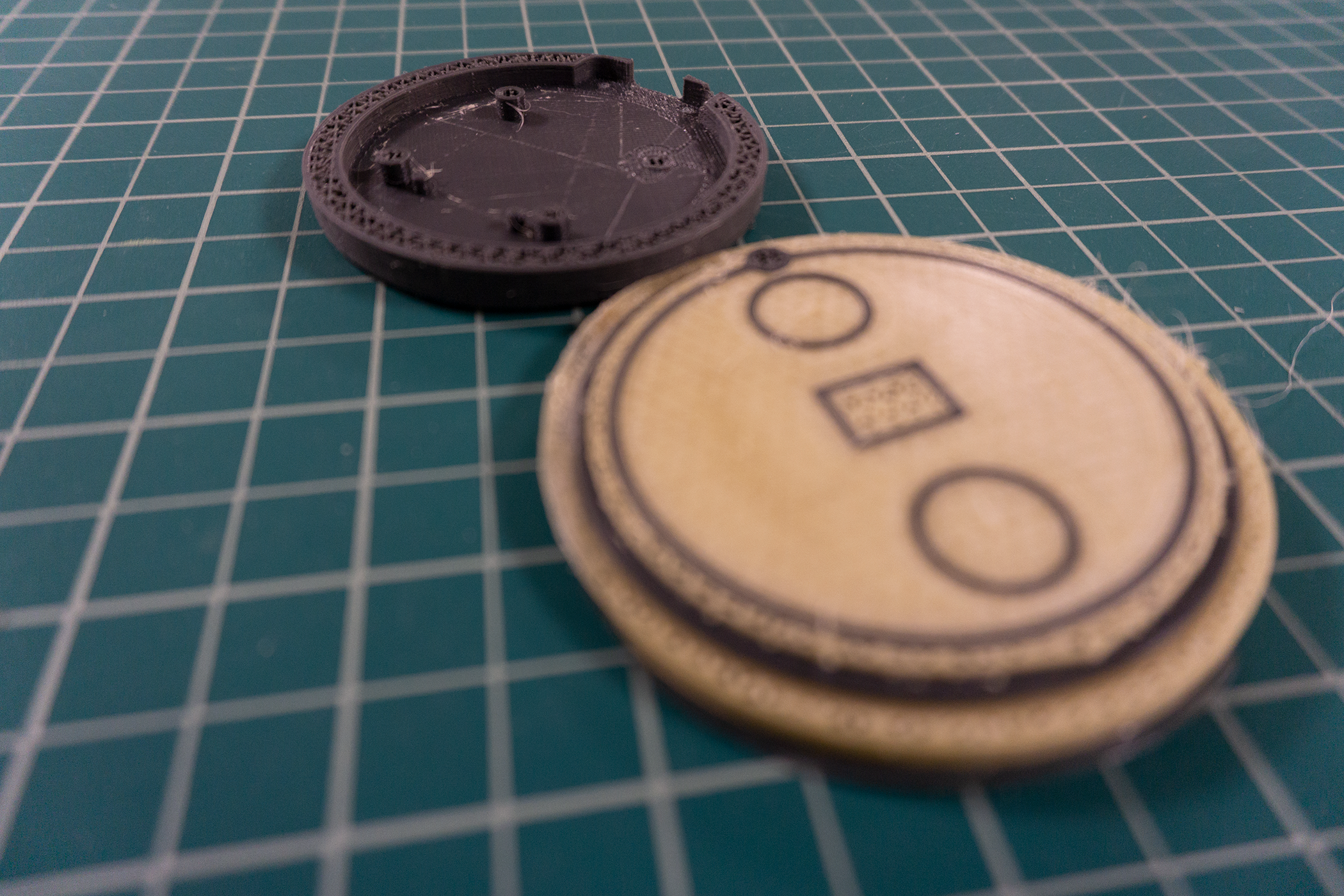
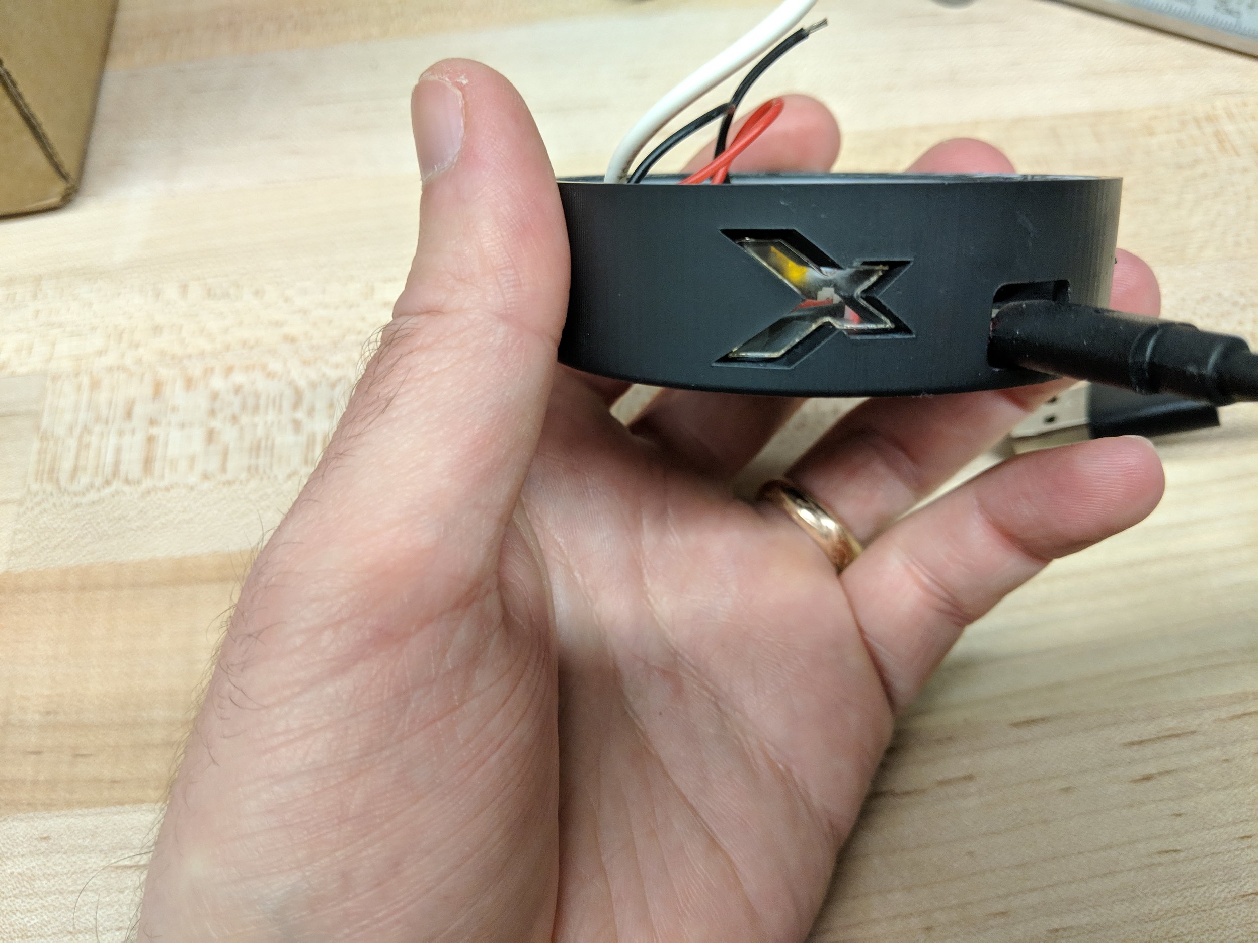
This version came out really well. Once again I needed to resize the PCB mounts, however, the USB port was perfect. I had tried a different light guide plane/angle for this X-strusion (har har). The fillets were really strong on the battery mounts and this infill/infill pattern turned out very nicely.
It Fits and Sits!
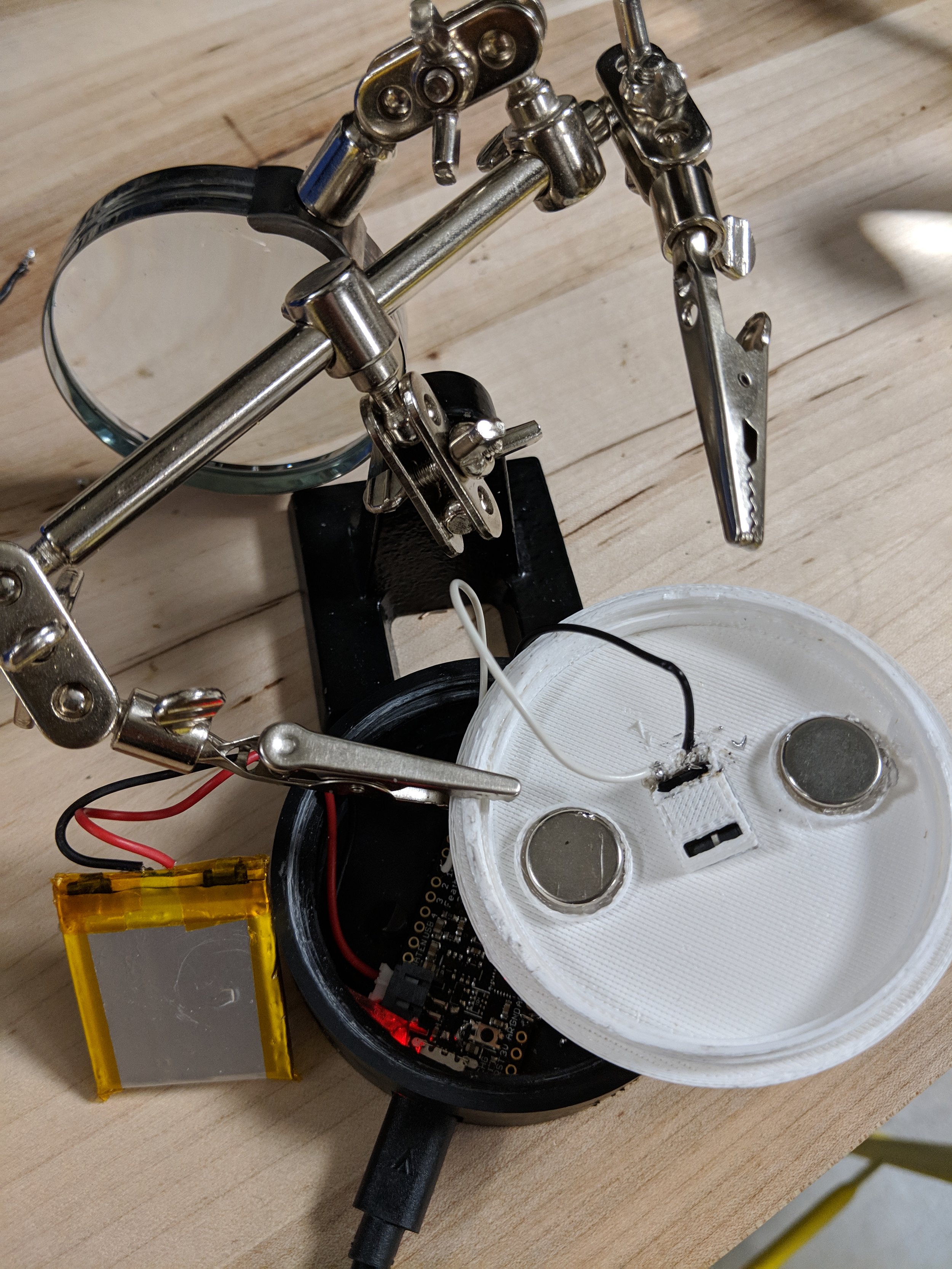
James had produced a couple iterations now and our dock/pod combo was working nicely! The detent lined up nicely with the pod and combining with the force of the magnets, the fit produced was excellent. An unexpected happy accident here was the feedback the magnetic force either confirms or denies the correct alignment of the base and pod interaction. This was a huge win.
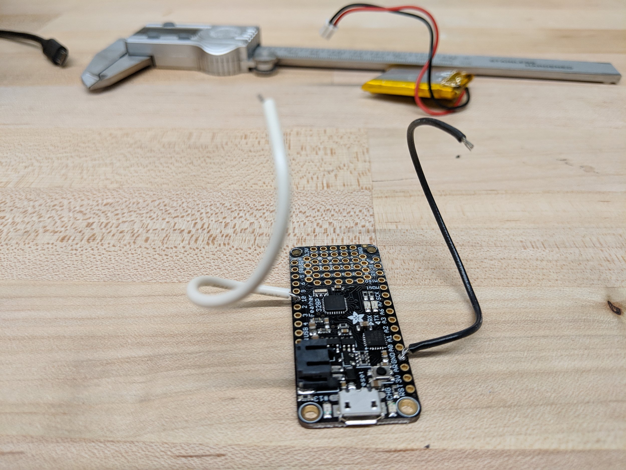
Hardware Electronics
Now that we were iterating mostly small details, we shifted gears to get our feathers talking to each other.

Code for Arduinos adapted from Brock Craft
// Dock Feather


const int ledPin = 13;

const int xmitPin = 10; // recvPin
void setup() {

  Serial.begin(9600);

  Serial.println("Board 511talk.send"); // recv

  pinMode(ledPin, OUTPUT); //recv, input_pullup

  pinMode(xmitPin, OUTPUT); //ledpin

}
void loop() {

  Serial.println("Sending high signal.");

  digitalWrite(ledPin, HIGH);

  digitalWrite(xmitPin, HIGH);

  delay(1000);

  Serial.println("Sending low signal");

  digitalWrite(ledPin, LOW);

  digitalWrite(xmitPin, LOW);

  delay(1000);

}
// Pod Reciever


const int ledPin = 13;

const int xmitPin = 10; // recvPin
void setup() {

  Serial.begin(9600);

  Serial.println("Board 511talk.send"); // recv

  pinMode(ledPin, OUTPUT); //recv, input_pullup

  pinMode(xmitPin, OUTPUT); //ledpin

}


void loop() {

   int sense = digitalRead(recvPin);

   if (sense == low) {

    Serial.println(received low)

    digitalwrite(ledpin,low)

   } else {

    digitalwrite(ledpin,high)

   }

}

I have surrendered to boring light guides…for a moment…
Final Forms
And for our last iterations, we printed on a higher fidelity FormLabs printer. We noticed that some of the tolerances changed, but overall the quality was much better. This was a surpisingly time consuming process and I’m happy to bring more physical objects into the universe with this practice.
Check out our video for the grand finale:
